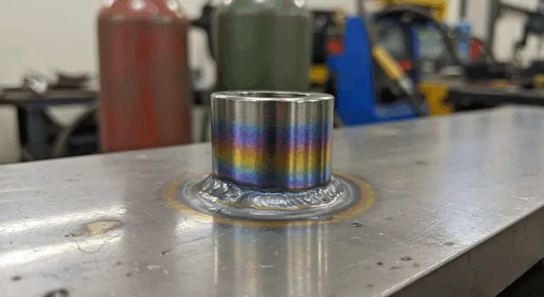
Understanding MIG Welding Spatter – Causes and Effects
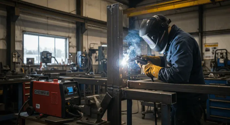
MIG welding spatter consists of tiny molten metal droplets ejected from the weld pool during the welding process. These droplets solidify and adhere to surrounding surfaces, creating an unsightly mess and potentially compromising weld integrity. Understanding what causes spatter formation is the first step toward effectively minimizing it.
Spatter typically stems from incorrect welding parameters, surface contaminants like dirt or oil, improper shielding gas mixtures, or deteriorated equipment. Any of these culprits can destabilize the arc, causing violent ejection of metal from the weld pool.
The consequences of spatter extend far beyond cosmetic concerns. Excessive spatter demands laborious cleanup, squanders valuable filler material, and can introduce structural weaknesses if left unaddressed. In professional environments, controlling spatter is essential for maintaining productivity, minimizing costs, and delivering quality welds that meet industry standards.
Factors Contributing to Spatter in MIG Welding
Multiple critical variables influence spatter formation. Adjusting the following variables can help minimize it:
-
Wire Feed Speed: If the speed is too fast, the wire hits the weld pool with excessive force. If it’s too slow, the wire can burn back toward the contact tip, creating an unstable arc.
-
Voltage and Amperage: An improper balance between voltage and amperage is a primary cause of spatter. Low voltage creates a sputtering arc, while excessively high amperage can cause turbulence in the weld pool.
-
Torch Angle and Movement: Hold the torch at a 5° to 15° angle from vertical in the direction of travel. Moving too quickly or too slowly can also increase spatter.
-
Arc Length and Stick out: An incorrect arc length (distance from tip to workpiece) or excessive stick out (wire extending from the tip) leads to an unstable arc and overheating.
-
Base Metal Condition: Contaminants like dirt, rust, or oil on the base metal vaporize violently under the arc, ejecting molten metal.
-
Shielding Gas and Wire Quality: Insufficient gas coverage, the wrong gas type, or low-quality wire can all destabilize the arc and increase spatter.
Choosing the Right Materials – Reducing Spatter
Selecting appropriate consumables provides the foundation for spatter reduction and stable arc performance.
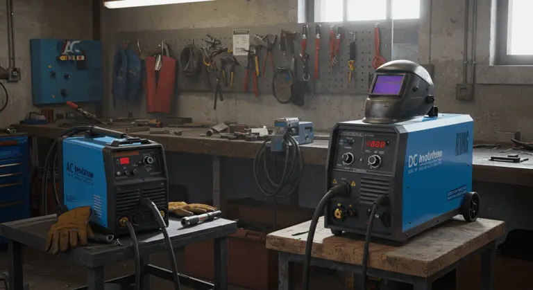
Begin by establishing the correct weld polarity for your specific application. For most MIG welding with solid wire, direct current electrode positive (DEEP) provides the best results with minimal spatter. When working with flux-cored wire, adhere strictly to manufacturer specifications—some varieties perform significantly better with direct current electrode negative (DEN).
Investing in premium welding wire significantly reduces spatter. High-grade wires maintain consistent diameter tolerances, exhibit superior feeding characteristics, and contain fewer impurities that could destabilize the arc. Though the initial investment may be higher, the reduced cleanup time and better weld quality usually justify the cost.
Your shielding gas selection proves equally decisive. Pure CO2, while economical, generates considerably more spatter due to its reactive nature. An argon/CO2 blend—such as 75% Argon and 25% CO2—provides excellent spatter control.
Cleaning Metal Surfaces Before Welding
Meticulous surface preparation before welding is one of the most effective strategies for spatter reduction. Surface contaminants vaporize explosively under the arc’s intense heat, propelling molten metal outward as unwanted spatter.
Start by eliminating all visible rust, scale, paint, and coatings from both the weld zone and ground clamp attachment points. Employ a dedicated stainless steel wire brush—keeping it separate from carbon steel brushes to prevent cross-contamination—or utilize an angle grinder equipped with a flap disc or wire wheel. For best results, extend your cleaning at least 1–2 inches beyond the intended weld area on all sides.
Following mechanical cleaning, tackle any residual oils or greases. Use suitable solvents like acetone or commercial degreases to eliminate these contaminants completely. Avoid chlorinated solvents—they decompose under arc heat, forming hazardous gases. Always observe safety protocols when handling solvents, including adequate ventilation and proper personal protective equipment.
For critical applications, consider a three-stage cleaning process:
-
Degrease: First, remove any oils or grease.
-
Mechanical Cleaning: Next, use a wire brush or grinder to remove oxides and scale.
-
Final Degrease: Degrease again to remove any contaminants introduced during the mechanical cleaning step.
Exercise particular caution regarding primer thickness when welding primed materials. Manufacturer specifications typically establish maximum allowable primer thickness for welding applications—exceeding these limits can trigger increased spatter and potential weld defects. Whenever feasible, weld on bare metal and apply protective coatings post-welding.
Execute cleaning immediately before welding commences. Clean metal surfaces—especially reactive metals like aluminum—rapidly develop fresh oxide layers or accumulate airborne contaminants when left exposed for extended periods.
Optimizing Welding Techniques to Minimize Spatter
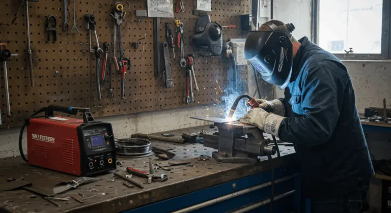
Developing refined welding techniques is essential for spatter minimization during MIG operations. Even with premium materials and pristine surfaces, subpar technique can still generate excessive spatter.
Begin by establishing optimal arc length. Maintaining consistent, appropriate distance between the contact tip and workpiece keeps the arc stable. As a fundamental guideline, position the contact tip approximately 3/8 to 3/4 inch (10-19mm) from the work surface. Too close risks wire stubbing; too distant compromises shielding gas coverage and destabilizes the arc.
Travel speed dramatically influences spatter generation. Excessive speed prevents proper fusion and creates turbulent weld pools. Conversely, sluggish movement generates excessive heat that promotes spatter formation. Listen carefully to your weld’s acoustic signature—a smooth, consistent bacon-frying sound indicates optimal parameters and technique.
Torch angle significantly impacts results. For most MIG applications, a slight drag angle of 5–15 degrees works best. This positioning enhances weld pool visibility while maintaining excellent gas coverage. Pushing the torch can occasionally reduce spatter on thinner materials but may compromise penetration on heavier sections.
Consider transitioning from globular to spray transfer mode when your equipment and materials permit. Spray transfer operates at elevated voltages and usually produces much less spatter, though it demands higher amperage and suits primarily thicker materials in flat or horizontal positions.
For flux-cored wires—which inherently generate more spatter—a drag technique often outperforms pushing. Additionally, verify correct polarity usage by consulting manufacturer specifications, as most self-shielded wires operate on DEN.
When excessive spatter occurs, don’t hesitate to halt operations and recalibrate your parameters. Sometimes a modest voltage increase can stabilize a spatter-prone arc, going against the common belief that lower voltage universally reduces spatter.
Adjusting Welding Parameters for Better Results
Precision parameter adjustment can significantly reduce spatter. Optimal settings generate stable arcs that transfer metal seamlessly from wire to workpiece with minimal turbulence.
Voltage is often the most important spatter-affecting parameter. Begin with manufacturer recommendations for your wire diameter and material thickness. If excessive spatter persists, try modest voltage reductions. However, insufficient voltage destabilizes the arc and may paradoxically increase spatter. Finding this balance requires methodical experimentation.
Wire feed speed operates in tandem with voltage—these parameters must achieve perfect balance. Excessive feed speed relative to voltage creates stubbing effects and spatter, while insufficient speed causes wire melt-back toward the contact tip. Generally, adjust wire feed speed first to achieve desired amperage for your material thickness, then fine-tune voltage for optimal arc characteristics.
For thicker materials, explore pulsed MIG processes if your equipment supports this capability. Pulsed MIG alternates between high and low current cycles, enabling spray-like metal transfer at reduced average currents. This approach provides lower heat input and much less spatter compared to conventional MIG.
Inductance settings—available on advanced welding machines—also helps control spatter. Higher inductance smooths the arc by moderating current rise rates when wire contacts the workpiece. This creates a gentler arc with reduced spatter, particularly beneficial for thin material applications.
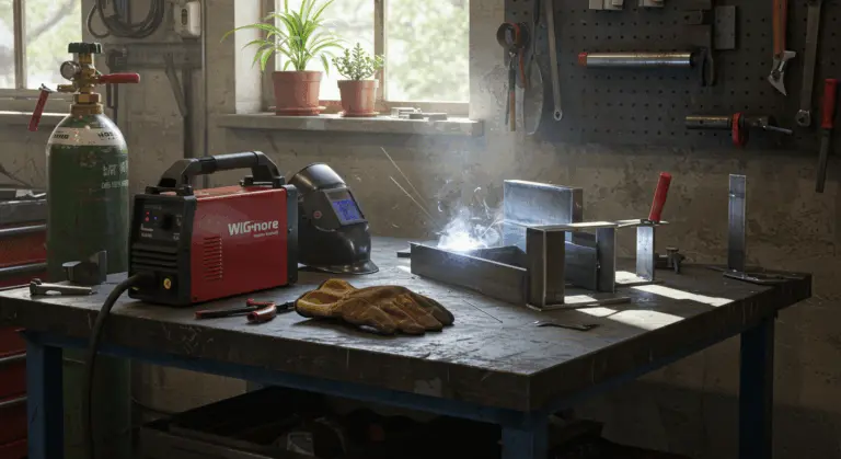
The Role of Shielding Gases in Spatter Control
Proper shielding gas selection stabilizes the arc and is essential for spatter control. Your primary options include:
-
Pure Carbon Dioxide (CO2): The most economical choice, but its reactive nature produces a turbulent arc and the most spatter. It is often chosen for its deep penetration on thick steel.
-
Argon/CO2 Blends: A mix of 75-80% argon and 20-25% CO2 is a popular all-purpose choice that significantly reduces spatter compared to pure CO2. Higher argon blends (e.g., 90/10) offer even cleaner results.
-
Trismic Gases: These premium blends, which add helium or oxygen, create extremely stable arcs for minimal spatter, ideal for thin materials or stainless steel.
Beyond selecting appropriate gas mixtures, ensuring proper flow rates is equally important. Insufficient flow compromises shielding and increases spatter, while excessive flow creates turbulence that draws atmospheric contamination into the shielding envelope. As a baseline guideline, establish flow rates of 20-30 cubic feet per hour (CFH) for most indoor applications, increasing for outdoor welding or drafty conditions.
Regularly inspect your gas delivery system for leaks or restrictions that could compromise shielding effectiveness. Even minor leaks introduce atmospheric contamination that destabilizes arcs and increases spatter. Similarly, maintain clean gas nozzles free of spatter accumulation that disrupts flow patterns.
Using Anti Spatter Products Effectively
Anti-spatter products are helpful tools for reducing MIG welding spatter. These specialized products create protective barriers that prevent spatter adhesion to surfaces, dramatically simplifying cleanup while safeguarding both workpieces and equipment.
Anti-spatter sprays are the most common type and are available in several formulations:
-
Water-based: Environmentally friendly, non-flammable, and generally safe for most welding environments.
-
Silicone-based: Provides excellent protection but must be completely removed before painting or coating to ensure proper adhesion.
When applying anti-spatter spray, apply a light, even coat to areas most likely to receive spatter:
-
The workpiece areas adjacent to the weld joint.
-
The nozzle of your MIG gun.
-
The contact tip.
For protecting the MIG gun nozzle and contact tip, anti-spatter gel or paste formulations often provide longer-lasting protection than sprays. These thicker products adhere better to vertical surfaces and withstand higher temperatures. Apply a thin layer to the inside and outside the nozzle, being careful not to block gas flow holes.
Some welders favor traditional methods—rubbing nozzles on soap bars or dipping hot nozzles in commercial compounds. These methods can be effective and economical for nozzle protection but offer no workpiece protection benefits.
Remember that anti-spatter products reduce cleanup time but don’t address spatter’s root causes. Use them as part of complete strategies that include proper parameter settings, refined technique, and pristine base materials. For optimal results, thoroughly clean surfaces before applying anti-spatter products—they perform best on contaminant-free surfaces.
Maintaining Equipment for Optimal Performance
Maintaining your MIG equipment properly is essential for spatter prevention. Conduct regular inspections of these essential components:
-
Contact Tip: Replace the tip when the opening becomes worn or irregular, as this causes arc instability.
-
Gas Nozzle: Keep the nozzle clean and free of spatter buildup, which can disrupt gas flow and cause contamination.
-
Gun Liner: A worn or clogged liner causes erratic wire feeding. Replace it if you notice binding or a scratching sound.
-
Drive Rolls: Ensure they are the correct type (e.g., V-groove for solid wire) and have the proper tension to feed the wire smoothly without slipping or deforming it.
-
Electrical Connections: Check that all connections, including the work clamp, are tight and on clean, bare metal to ensure a stable electrical circuit.
Testing and Adjusting Settings for Spatter Reduction
Systematic testing and parameter adjustment is the final step in minimizing MIG welding spatter. This methodical process helps identify optimal parameters for your specific equipment, materials, and applications.
Create test pieces from identical materials you’ll use for actual projects. Configure your machine according to manufacturer recommendations for your wire type and diameter, then execute systematic test welds while methodically adjusting individual parameters.
To find the ideal settings, follow a methodical approach:
-
Establish a Baseline: Start with the manufacturer’s recommended settings for your material.
-
Adjust One Variable: Make a series of test welds, adjusting only one parameter at a time (e.g., voltage) in small increments.
-
Isolate and Refine: Once you find the best voltage, keep it constant and begin adjusting the wire feed speed to fine-tune the arc.
Experiment with stick out length—the distance wire extends beyond the contact tip—as this significantly impacts spatter formation. Generally, shorter stick outs of 3/8 to 1/2 inch (10-13mm) provide superior control and reduced spatter for short-circuit transfer. Spray transfer may benefit from slightly longer stick outs of 1/2 to 3/4 inch (13-19mm). Never exceed 1 1/4 inch stick out, as this causes excessive wire heating and instability.
If your machine features adjustable inductance or arc control settings, test various levels to determine optimal performance for your application. Higher inductance typically smooths arcs and reduces spatter but may influence penetration and bead profiles.
Document your discoveries in a personal welding reference chart, recording material types, wire specifications, gas mixtures, and optimal settings. This useful reference saves time and ensures consistency across future projects.
Remember that environmental variables like temperature and air currents can affect results, so remain prepared to make minor adjustments even after establishing baseline settings. Your goal is developing intuitive understanding of how your equipment responds to various adjustments, enabling rapid parameter optimization for any welding challenge.