Understanding MIG Welding Settings for 1/8″ Steel
When tackling 1/8-inch (0.125″) steel, these baseline settings serve as your starting point—though fine-tuning for your specific conditions remains essential:
Successful MIG welding hinges on recognizing when adjustments are necessary. Arc stubbing into the workpiece? Bump up your voltage. Arc running too hot or behaving erratically? Dial it back.
Key Parameters: Voltage and Wire Feed Speed
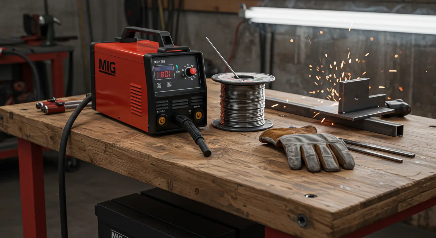
Voltage and wire feed speed (WFS) form the foundation of successful MIG welding on 1/8 inch steel. These parameters work together, controlling arc characteristics, penetration depth, and the overall integrity of your weld.
Voltage governs arc length and bead width, directly influencing how deeply you penetrate the material. Wire feed speed (WFS)—measured in inches per minute (IPM)—dictates the volume of filler metal flowing into your joint.
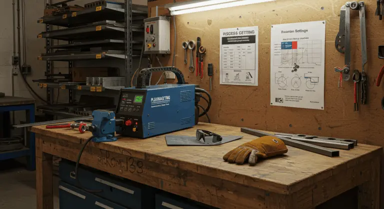
Contemporary welding machines typically include reference charts suggesting initial settings based on material thickness and wire diameter. Use these as your starting reference. Some advanced machines offer synergic MIG programs that automatically adjust parameters as you change one setting.
Beyond these primary settings, several secondary parameters can enhance performance, though they are not essential for basic projects:
-
Inductance: Controls arc stiffness.
-
Burn back: Prevents the wire from sticking to the contact tip.
-
Pre- / Post-Gas Flow: Manages shielding gas at the start and end of the weld.
-
Advanced Options: Features like crater fill, start slope, and pulse settings for more complex projects.
Choosing the Right Shielding Gas
Your choice of shielding gas significantly affects weld quality when working with 1/8 inch steel. The right mixture shields your weld pool from atmospheric contamination while influencing arc behavior and penetration characteristics.
The most common choice for MIG welding mild steel at this thickness? A 75% argon and 25% CO₂ blend, known as C25. This mixture provides excellent arc stability, robust penetration, and minimal spatter—argon smooths the arc while CO₂ drives deep fusion.
Budget-conscious welders sometimes choose 100% CO₂. While your wallet will thank you, pure CO₂ brings trade-offs: increased spatter, less stable arcs, and wider, more convex bead profiles.
When precision matters most or aesthetics take center stage, consider a trismic gas containing argon, CO₂, and a small percentage of oxygen. This premium mixture can further reduce spatter and improve weld pool fluidity, though it comes at a higher cost. For any gas, maintain a flow rate of 20-25 cubic feet per hour (CFH) for optimal coverage when welding 1/8 inch steel.
Fine-Tuning Your MIG Welding Settings
Baseline settings are just your starting point for 1/8 inch steel projects. Skill develops through fine-tuning—adapting to your specific welding position, joint geometry, and environmental variables.
Start with test welds on scrap material matching your project steel. Pay attention to the arc sound and appearance.
Scrutinize your test welds with a critical eye. Perfect beads showcase even ripples, seamless edge tie-in, and a gently convex profile.
Embrace incremental changes—0.5 volts or 5-10% wire feed adjustments at a time. This methodical approach prevents overcorrection and guides you toward optimal settings.
Common Issues and Solutions
Identifying and resolving common welding challenges will significantly improve your results. This diagnostic guide helps you troubleshoot effectively:
| Issue | Symptoms & Causes | Solution |
|—|—|—|
| Excessive Voltage | Unstable, erratic arc; potential burn-through. | Reduce voltage in 0.5–1V increments. |
| Insufficient Voltage | Arc “stubs” into the workpiece; poor fusion. | Increase voltage until the arc is smooth. |
| Excessive Wire Feed | A convex, “ropey” bead with undercutting. | Reduce wire feed speed by 5–10%. |
| Insufficient Wire Feed | A flat or concave bead with inadequate fill. | Increase wire feed speed incrementally. |
| Poor Gas Coverage | Porosity (holes), excessive spatter, sooty appearance. | Check flow rate (20-25 CFH), check for leaks, shield from drafts, and clean the material. |
| Inconsistent Travel Speed | Variations in bead width and penetration. | Maintain a steady pace (~10–12 IPM), keeping the weld puddle size consistent. |
Practical Tips for Successful MIG Welding
Settings alone don’t guarantee success. These practical strategies will improve your MIG welding results on 1/8 inch steel, connecting technical knowledge with practical application.
-
Understand the Process: Visualize how the arc melts the base metal and filler wire to create a fluid puddle. Understanding this process helps you adjust settings more effectively.
-
Experiment on Scrap: Create test welds with various settings, labeling each one. Break or cut the samples to examine penetration and build confidence.
-
Listen to the Arc: A smooth, consistent sizzle indicates good parameters. Popping or sputtering signals a problem that requires adjustment.
-
Clean the Material: Remove mill scale from the steel with a grinder or wire brush before welding to promote better fusion and reduce defects.
-
Consider Advanced Consumables: For production work, metal-cored wires can offer higher deposition rates and less spatter. Pulsed MIG provides exceptional control but requires more advanced equipment.
-
Ensure Proper Setup: Clamp workpieces firmly to prevent movement and position yourself comfortably to maintain a consistent travel angle and speed.
Welding Techniques for 1/8″ Steel
Welding 1/8 inch steel demands specific techniques tailored to achieve professional results across various joint configurations and positions. Learning these techniques leads to more consistent results.
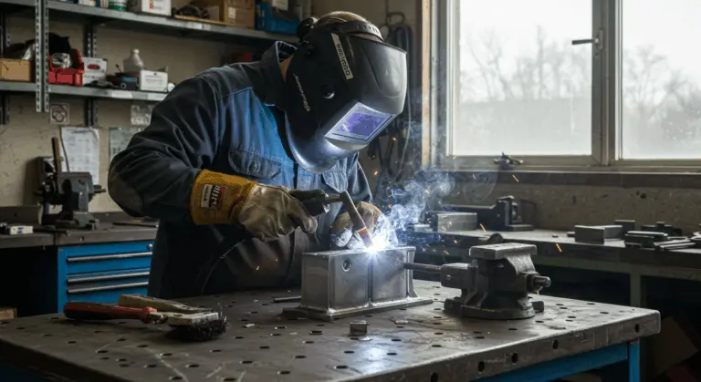
For flat position work on 1/8 inch steel, establish a 10-15 degree work angle in your travel direction, with the gun angled slightly backward in a drag technique.
Vertical seams benefit from the uphill technique, delivering superior penetration and strength in 1/8 inch steel. Employ gentle side-to-side weaving, pausing briefly at each edge for proper tie-in.
Horizontal welding requires a 0-15 degree upward gun angle to combat gravity’s pull on the molten puddle. This subtle adjustment prevents weld metal from sagging along the joint’s lower edge.
Facing gaps or poor fit-up in 1/8 inch material? Slow your travel speed and consider light weaving to build material at the edges.
Evaluating Weld Quality
Quality assessment of your 1/8 inch steel welds ensures both structural integrity and aesthetic standards are achieved. Visual inspection combined with advanced testing methods validates your parameter optimization.
Visual inspection serves as your primary quality checkpoint. Properly executed MIG welds on 1/8-inch steel should display:
Color tells its own story about weld quality. On mild steel, expect the weld and heat-affected zone to appear silver to light golden brown.
Sound welds demand complete fusion throughout their cross-section. Test penetration on practice pieces by breaking or cutting perpendicular to the weld length.
Critical applications may demand rigorous testing beyond visual inspection. Non-destructive methods like ultrasonic or X-ray examination reveal internal defects invisible to the naked eye—particularly vital for structural or pressure-containing welds.
When defects surface, systematically adjust welding parameters based on specific issues identified. Porosity typically points to gas coverage problems, while lack of fusion suggests insufficient heat input or flawed technique.