Basics of Fillet Welds – What You Need to Know
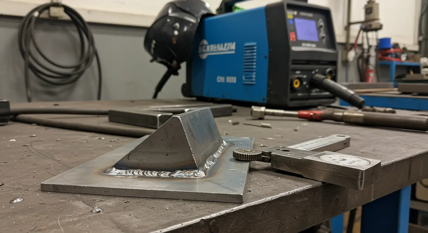
Fillet welds represent one of the most versatile and widely used joining methods in metal fabrication. These welds unite two surfaces at an angle, creating a distinctive triangular cross-section that’s both structurally sound and aesthetically clean. You’ll find them primarily in lap joints, T-joints, and corner connections—applications where their strength shines without demanding complex edge preparation.
The basic fillet weld symbol communicates essential information through several key components:
-
Reference Line: The horizontal baseline for the symbol.
-
Arrow Line: Points to the joint to be welded.
-
Tail: An optional element for specifications like the Welding Procedure Specification (WPS).
-
Fillet Weld Symbol: A right triangle indicating the weld type.
These welds are essential for professionals in welding, fabrication, and engineering. These welds form the structural backbone of countless assemblies, providing reliable strength when executed with precision. Standardized symbols on engineering drawings ensure clear communication among designers, engineers, and welders, minimizing fabrication errors.
The Anatomy of a Fillet Weld Symbol – Key Components
At the heart of every fillet weld symbol lies a simple yet powerful triangle—a geometric representation of the weld’s actual cross-section. This triangle finds its home on a horizontal reference line, which serves as the anchor point for all accompanying information.
The horizontal reference line forms the symbol’s foundation, with an arrow line extending outward to pinpoint the exact joint location. Here’s where positioning becomes critical: a triangle below the reference line signals an arrow-side weld, while placement above indicates the opposite side.
The tail—that optional extension from the reference line—carries supplementary instructions, such as welding process codes or reference standards. These components collectively provide a complete guide for executing welds to design specifications.
Dimensions on a Fillet Weld Symbol – Understanding Size
Weld size is the most critical dimension, typically defined by either leg length or throat thickness. Leg length (z) defines the dimensions of the weld’s triangular sides—a measurement favored by inspectors for its straightforward verification using standard weld gauges.
Throat thickness (a) represents the shortest distance from the weld root to its face, typically measuring approximately 0.7 times the leg length for standard welds. When you see a size dimension positioned left of the weld symbol—say, a ‘6’—you’re looking at a 6mm leg length specification.
While leg length is preferred for measurement convenience, throat thickness drives the strength calculations that matter most to structural integrity. Engineers often design for throat thickness and then specify the corresponding leg length on drawings. Understanding this relationship is essential for proper execution and inspection.
Indicating the Fillet Weld Size – Methods and Standards
Industry standards such as BS EN ISO 5817 establish precise tolerances for weld dimensions, acknowledging the realities of field conditions. Consider a 10mm leg length weld: depending on quality requirements, acceptable leg length variations might range from ~2.5mm for stringent applications to ~3.4mm for moderate quality standards.
Quality control relies on specialized tools—fillet weld gauges and digital calipers—to verify these critical dimensions. Unequal leg lengths, though potentially within tolerance, create additional costs: increased material consumption, elevated heat input, and unwanted distortion. Proper size specification and verification are therefore essential for both quality and economy.
Locating the Weld on the Joint – Positioning Symbols
The fundamental rule is simple: symbol position relative to the reference line determines weld location. Below the line? Arrow side. Above the line? Opposite side.
Special Cases: Change of Direction and Multiple Arrows
Complex geometries require more detailed solutions. When dealing with direction changes or multiple joint locations, a single welding symbol can deploy multiple arrows—each precisely targeting its designated weld location.
This approach is valuable when specifying welds that navigate complex geometries, like intermittent or staggered patterns. Multiple arrows allow designers to precisely map weld segments, while the standard above/below placement on the reference line still dictates arrow-side or other-side application.
Consider a complex assembly where, separate arrows can point to each edge that requires welding, with symbols specifying the weld type and size for each location. Such detailed specification eliminates guesswork for fabricators while maintaining design integrity.
Intermittent Fillet Welds – Understanding Gaps & Segments
Intermittent fillet welds—often called skip welds—provide an effective solution for specific applications. These consist of alternating welded segments and deliberate gaps, offering adequate strength while consuming less filler material and generating reduced heat input.
The specification appears to the right of the symbol with straightforward dimensions: the weld segment length, a hyphen, and the pitch (center-to-center spacing). For example, ’20-60′ specifies 20mm long weld segments with a 60mm pitch, resulting in 40mm gaps.
This systematic approach ensures pattern consistency, offering material and labor savings while meeting structural needs. However, avoid these welds when hermetic sealing is essential or fatigue loading dominates your design concerns.
Chain Intermittent Welds – Characteristics and Uses
Chain intermittent welds create a distinctive pattern where segments on both sides of a joint align directly opposite each other. Picture chain links, and you’ll grasp the visual concept—this configuration excels at balancing stress distribution across the joint.
The main advantage is even stress distribution with significantly less filler material and heat input compared to continuous welds, which minimizes distortion and improves efficiency. On symbols, the length and pitch dimensions are placed to the right of the weld symbols on both sides of the reference line.
These welds work well in structural applications where full-strength continuous welds would represent overkill, such as in certain types of frames, brackets, or stiffeners. The controlled flexibility they provide can improve fatigue resistance in certain assemblies. However, proper engineering analysis should always determine if this weld type is appropriate for the specific loading conditions of the application.
Staggered Intermittent Fillet Welds – Overview
Staggered intermittent fillet welds use a different approach, featuring an offset pattern where weld segments on one side align with gaps on the opposite side. This chess-like alternating arrangement delivers distinct advantages over its chain intermittent counterpart.
Staggered welds are excellent for stress distribution, spreading loads even more effectively along joint lengths. The offset pattern minimizes stress concentration points—areas where failures often start, and overall joint strength can be improved. On welding symbols, staggered intermittent welds are indicated by adding a stagger symbol (resembling a zigzag line) alongside the length and pitch dimensions for the welds on each side of the reference line.
These welds are particularly useful for distortion control and cyclic loading applications, as the offset pattern prevents continuous stress paths. In tight spaces, the staggered arrangement often improves welding access where continuous welds would be challenging, offering a good balance of material use, strength, and practicality.
Supplementary Weld Symbols – Additional Information
Supplementary symbols extend far beyond basic weld type identification—they communicate the nuanced requirements that distinguish good welds from excellent ones. These symbols work alongside primary symbols to ensure every design specification finds its way to the shop floor.
Common supplementary symbols provide additional instructions:
-
Contour Symbols: Indicate if the weld face should be flat, convex, or concave.
-
Finish Symbols: Specify the finishing method (e.g., grinding, machining).
-
Field Weld Symbol: A flag indicating the weld is made on-site.
-
All-Around Symbol: A circle indicating the weld continues around the entire joint.
-
Melt-Through Symbol: Shows that complete joint penetration is required.
-
Process Specification: Included in the tail to specify the welding process (e.g., SAW, GMA).
Wrapping It Up – Key Takeaways on Fillet Weld Symbols
Understanding fillet weld symbols is a fundamental skill for welding, fabrication, and engineering professionals. Critical information flows through strategic symbol placement: below the reference line for the arrow side and above for the opposite side, ensuring clear communication of the weld’s location.
While leg length (positioned left of the symbol) simplifies inspection, remember that throat thickness ultimately determines structural strength. For intermittent welds, length and pitch dimensions (to the right of the symbol) define the segment pattern.
Standards like ANSI/AWS A2.4 provide the foundation for consistent interpretation, These symbols form a universal language that bridges design intent and fabrication reality. Understanding them allows professionals to execute welds precisely as designed, ensuring structural integrity and quality.